
Mining Dust Suppression Nozzles: Sizing Spray Bars That Catch Respirable Dust
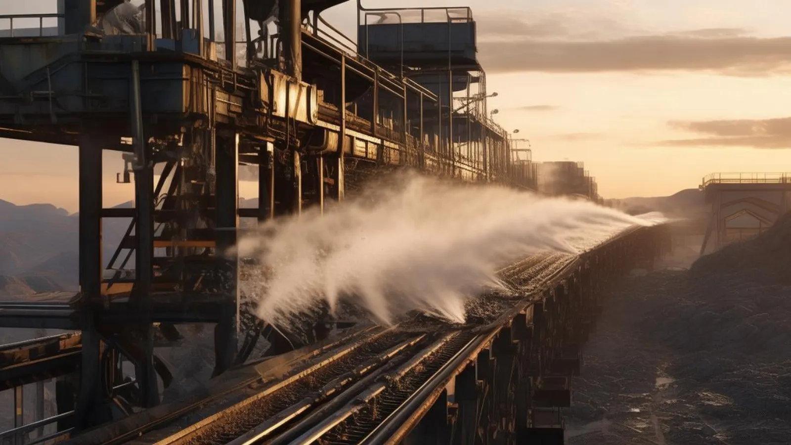
Table of Contents
A 1000 mm granite belt feeds a jaw crusher at 250 tonnes per hour. Personal sampling at the transfer point later reads 1.8 mg/m3 of respirable dust. Typical published action levels for respirable crystalline silica sit between 0.025 and 0.05 mg/m3. The spray bar above the chute carried eight nozzles on the drawing. A maintenance walk finds two plugged and three worn into hollow cones.
The crew reacts the way crews react and opens the valve wider. Water climbs past one percent of tonnage, the load turns to slurry, and it drags across the drive pulley. Belt slip, carryback and a blinded screen follow the attempt. The failure pattern in mining nozzles runs in exactly two directions, too dry and too wet. Both trace back to one missing arithmetic of droplet match, nozzle count and water rate.
The Snapshot
- 1 to 5x droplet-to-particle diameter ratio for capture of respirable dust below 10 um
- 20 to 100 um droplets from internal-mix air atomizing nozzles at 2 to 6 bar
- 2 to 4 nozzles per meter on transfer point spray bars across 2 to 3 drop zones
- 0.5 to 1.0 percent of tonnage as the total water ceiling before belt slip risk climbs
Why Transfer Points Throw the Dust
Dust leaves a belt where the material changes velocity. The load rides the belt at line speed. Then it free-falls off the head pulley and slams into the impact plate or the next belt. Every impact shoves a puff of air out of the falling stream. That air carries fines with it.
Typical industry practice puts the worst emission at the discharge side. The material separates from the belt surface there, and the air it entrained keeps going. Three variables set the emission: drop height, line speed and fines fraction. A high drop at fast line speed pushes a far deeper air curtain through the falling stream than a short drop at walking pace.
Crushed granite with 15 percent passing 100 mesh creates a finer plume than rounded river gravel at the same tonnage. Crusher outlets concentrate the problem. The crusher grinds fresh surfaces, and the discharge is dry, hot and moving fast.
The plume moves with the material, not against it. That is the design insight most spray bars miss. The best mining nozzles sit inside the capture zone where the air jet is still coherent. On most belts that window is 0.3 to 1.0 m below the tail. Spray across the falling stream, not straight down onto it.
Match the Droplet to the Particle
Water captures dust mostly by inertial impaction. A particle rides the air stream around a droplet unless it is too heavy to turn. When it cannot turn, it hits the liquid and leaves the airstream. Capture efficiency peaks when droplet diameter is roughly 1 to 5 times particle diameter.
Typical industry practice puts that ratio band between 1x and 5x for the target fraction. A 1000 um full-cone drop does not catch a 2 um silica particle well. The particle dodges the drop and stays suspended. A 20 um drop catches it far more often. Fine drops beat big drops for respirable dust.
That single fact separates a control system from a sprinkler. Size the respirable band first, from the particle outward. Then check that the coarse fraction still gets wetted. A second, coarser row often handles the big fraction cheaply.
| Target fraction | Particle size | Matched droplet band (1 to 5x) | Practical nozzle class |
|---|---|---|---|
| Coarse road dust | 50 to 200 um | 50 to 1000 um | Single-fluid full cone or flat fan |
| Screen and stockpile fines | 10 to 50 um | 10 to 250 um | Fine full cone or low-pressure air assist |
| Respirable at transfers | 1 to 10 um | 1 to 50 um | Internal-mix air atomizing |
| PM10 plumes in chutes | up to 10 um | 20 to 100 um | Air atomizing or dry fog |
Read the table and then walk your own transfer. Most existing bars deliver the first row. The respirable fraction lives in the third row.
Respirable Dust Sets the Hardware
PM10 sampling covers particles up to about 10 um. Many published sampling curves put the respirable convention near 4 um for the thoracic fraction. Crushing and screening generate fresh particles across that whole band, continuously.
A spray that controls only the visible plume leaves the invisible fraction untouched. That is where silica exposure questions live. Single-fluid pressure atomization has a hard ceiling here. Typical industry practice puts single-fluid full-cone droplets in the 100 to 1000 um range at 3 to 10 bar. Pushing pressure higher mostly adds drift and bounce, and rarely adds sub-50 um drops.
Internal-mix air atomizing nozzles break that ceiling. They put compressed air through the liquid passage. The energy for breakup comes from the air, not from pumping water to 30 bar. Typical published practice puts their droplets at 20 to 100 um, at only 2 to 6 bar of water and air pressure.
That is why crusher outlets increasingly get air-assisted rows. The rows sit on the two or three worst drop zones. Plain full-cone mining nozzles cover everything else. The mix is deliberate. Coarse water knocks down the big fraction cheaply, and atomized mist strips the respirable fraction where it matters.
Single Fluid, Air Assist, Dry Fog: Choosing the Row Type
Three families of dust suppression nozzles do the work at mining dust sources, and each has a clear duty.
Single-fluid full cone covers belt cleaners, chute walls, loading faces and stockpile dusting. It is cheap per installed nozzle. It tolerates dirty water. It puts coarse film where coarse film is enough. Do not let it be the only row over a granite transfer, because it cannot build a respirable capture band.
Air atomizing fits transfer drop zones, crusher discharge chutes and screening inlets. One internal-mix air atomizing nozzle screws into a standard pipe tee. Retrofit into an existing bar therefore needs no new plumbing layout.
It needs clean, dry air at 2 to 6 bar. An undersized compressor or a wet airline kills the droplet claim. If the plant has no compressed air capacity near the chute, that is a civil and electrical cost, not a nozzle cost.
Dry fog is the fine end of the air-assisted family. It runs higher air-to-liquid ratios, so the envelope stays near 10 to 40 um. Typical dosing stays in the tenths of a percent of tonnage. Material handling barely notices it. See the dry fog case study for a limestone transfer where the fog row cut respirable readings while the belt kept its traction.
The site’s general dust suppression nozzle guide covers pile and stockpile duty in more depth. This guide stays on hard rock, coal and aggregates inside the plant envelope.
Sizing the Spray Bar: Count, Spacing, Placement
Spray bars at transfer points commonly carry 2 to 4 nozzles per meter. The full arrangement covers 2 to 3 drop zones. It does not treat every belt in the circuit. Typical industry practice puts the spacing target at overlapping edge-to-edge coverage of the falling stream.
Placement beats count. On a head pulley transfer, mount the bar 0.3 to 0.9 m below the tail edge. Angle the rows so drops hit the stream from the sides and from behind the discharge. A bar mounted upstream, over the carrying belt, mostly washes the belt. Belt washing is how carryback and pulley slip start.
| Bar length | Nozzles at 2/m | Nozzles at 4/m | Water at 6 L/min per nozzle | Comment |
|---|---|---|---|---|
| 1.0 m | 2 | 4 | 12 to 24 L/min | Narrow chute, single drop zone |
| 1.2 m | 2 or 3 | 4 to 5 | 15 to 30 L/min | 1000 mm belt, discharge side |
| 1.6 m | 3 or 4 | 6 | 18 to 36 L/min | Wide belt or double drop zone |
Two details separate a working bar from one that merely looks identical. First, nozzle count must survive plugging. A row of 4 with 20 percent plugged is a row of 3. Capture then falls faster than the count suggests. Second, the orifice must be sized for flow at the real header pressure.
Ordering 2.5 L/min nozzles for a header that only delivers 3 bar means every row underdelivers. The design point and the delivered point drift apart, quietly, and nobody notices until the exposure report lands. Keep a pressure gauge at the far end of each bar during commissioning, and log the reading with the nozzle schedule.
Worked Example: Crusher Outlet Spray Bar
Take the 250 t/h granite transfer from the opening. The 1000 mm belt drops 1.6 m into a vibrating feeder. Sampling shows the respirable plume concentrated within 1 m of the impact point. Two drop zones therefore get treated: the belt tail and the feeder inlet.
Step one, fix the water ceiling. Typical industry practice puts total dosing below 0.5 to 1.0 percent of tonnage. At 250 t/h, one percent is 2.5 m3/h, about 42 L/min. Set the design dose at 0.6 percent, so 25 L/min total. That leaves 17 L/min of margin before slip risk climbs.
Step two, size the nozzle count. Fit two bars, each 1.2 m, each carrying 4 nozzles. That is 3.3 nozzles per meter, inside the 2 to 4 band, with plugging redundancy. Each nozzle then delivers 25 divided by 8, about 3.1 L/min.
Step three, set the droplet match. The belt tail bar gets four internal-mix air atomizing nozzles. Rate them at 3 L/min, at 4 bar water and 4 bar air. They produce roughly 20 to 60 um drops against the respirable fraction. The feeder inlet bar gets four full-cone mining nozzles at 3 to 4 L/min each, catching the coarse bounce-off cloud.
Step four, check services. Total demand is 25 L/min of water. The atomizing row needs roughly 40 to 50 Nm3/h of free air. Walk the belt after start-up, first with water off, then on. The plume should die at the tail within one second of the valve opening.
If it lags, the bar sits too high or too far forward. More water will not fix geometry.
The Water Budget: Dose Limits and Belt Slip
Water is cheap per litre. It is expensive per tonne of downstream trouble. Typical industry practice keeps total dust suppression dosing below about 0.5 to 1.0 percent of conveyed tonnage in the crushing and screening circuit. Above that band, material stops behaving like aggregate. It starts behaving like slurry.
Belt conveyor dust control and belt health compete for the same water budget. The pulley does not care how good the exposure numbers look.
The failure sequence repeats at sites that chase visible dust with valves instead of arithmetic. Load weight climbs, then traction on the drive pulley drops. The belt slips, and the slip heats the splice. Carryback rides the return side into the tail pulley and lifts the belt off the idlers.
Screens blind next, because wet fines plate the openings. Stackers plug. Each of these costs more than the dust ever did. Each started as dust control.
| Dose as percent of tonnage | Typical behaviour |
|---|---|
| Up to 0.3 percent | Safe band for most fog and single-fluid rows |
| 0.5 to 1.0 percent | Normal working band for transfer wetting |
| Above 1.0 percent | Slip, carryback and screen blinding risk rises sharply |
| Above 1.5 percent | Handling problems even before winter freezing |
Coal and oil sands duty sits lower on the scale. The material is finer and more hydrophobic. Aggregates tolerate more water before handling breaks down. Silica exposure control still wants less water and better droplets.
The correct answer to more dust is almost never more litres. It is a smaller droplet, a better-placed row, and a skirt that keeps the plume inside the capture zone.
Wetting Agents for Hydrophobic Coal Dust
Coal dust surfaces resist water. Plain droplets bead and roll off. A hydrophobic pile can read wet on the surface while the fines underneath stay dry and airborne. Mining nozzles on coal therefore fight surface chemistry, not just physics.
Typical published data puts plain water at about 72 mN/m of surface tension. Surfactant dosing drops treated water into the 31 to 38 mN/m range. That is where penetration of coal and hydrophobic fines starts to work.
A lower-tension drop spreads instead of beading. It wicks into micro-cracks in lumps and bonds fines into the matrix. The practical effect is that you capture the same respirable mass with less total water. That pulls you back down from the slip band. Typical dosing of surfactant into the spray line runs at 0.05 to 0.5 percent of the water stream, metered by a proportioning pump.
Two cautions belong in the spec. First, most surfactants are sensitive to dilution and shear. Inject upstream of the nozzles, then confirm the metered dose at the bar, not at the drum. Second, foaming in the header and drip at shutdown will punish a badly drained circuit. Fit check valves or drip-free tips on every nozzle, and slope the pipework.
Coal prep plants pair wetting agents with air atomizing rows on conveyor transfers far more often than with plain sprinklers. The chemistry and the droplet size work together.
Longwall and Continuous Miner Ancillary Sprays
Underground coal runs a different spray architecture. The primary water line travels through the shearer or the continuous miner. Nozzles sit in three families: pickup or in-drum sprays, ancillary or exhaust sprays, and ventilation sprays at the face returns.
Ancillary mining nozzles catch the dust the machine throws into the cabin-side airstream. Typical published practice puts external ancillary spray nozzles on sheared coal at roughly 1 to 2 gpm per nozzle. Inlet pressure at the nozzle sits around 20 to 100 psi, depending on the machine and the roof strata.
Pickup sprays inside the drum run at higher pressure and take brutal abrasion. That is why hardened orifices and replaceable inserts are standard there. Continuous miner ancillary sprays sit on the conveyor mast and the dust collector exhaust. Their nozzle count matters less than keeping orifices from scaling with hard mine water.
Two failure patterns repeat in longwall water audits. The pumping station delivers pressure at the header but not at the face. Pipe friction and elevation eat 20 to 30 percent of set pressure by the time the line reaches the machine.
Each nozzle then runs under rated flow, droplets coarsen, and the capture band collapses. Size the pump for the pressure at the last nozzle, never the first. The second pattern is aim: nozzles pointed toward the operator rather than the cutting interface. That moves silica-laden droplets into the breathing zone.
Nozzle Wear, Materials and Filtration
Mining nozzles live in the worst slurry water on site. Reclaimed transfer-point water returns full of fine solids. A half-millimetre orifice passing that water erodes in weeks if it is soft brass.
Erosion changes everything downstream of the orifice. Flow rises, the pattern fattens, and the droplet spectrum coarsens. The spray still looks alive from the catwalk. The capture band is gone, and the respirable readings quietly climb back.
Wear practice has one rule: use hardened orifice mining nozzles wherever slurry abrasives are present. Tungsten carbide and technical ceramic inserts outlast brass by a wide margin in reclaimed-water duty. Cost per nozzle runs two to five times brass. Cost per hour of calibrated flow usually runs far lower.
Filtration does the rest of the work. Typical transfer-point circuits run a 100 mesh disc or self-cleaning filter ahead of air-assisted rows. A coarser screen protects plain full-cone bars. Strainers at each bar let one dirty leg be isolated without shutting the crusher circuit.
Record filter differential pressure weekly. A plugged filter looks exactly like a worn nozzle at the bar. The two failures push water flow in opposite directions, and only the gauge tells them apart.
Air quality deserves the same discipline. Internal-mix air atomizing nozzles have small air passages. A wet airline dumps condensate into them, causing corrosion, ice in cold plants, and intermittent spitting. Drain pots and a point-of-use dryer keep the droplet claim true through winter.
Common Failure Modes and Field Fixes
Most complaints resolve into five patterns. Each has a field test that takes one shift.
Plume stays visible with water on. Geometry failure. The mining nozzles sit outside the coherent air jet, above the belt instead of at the drop, or they spray against the induced airflow. Move the bar into the 0.3 to 0.9 m window below the tail. Angle rows into the stream.
Readings drop but exposure stays high. Droplet mismatch. The system controls the visible cloud while the sub-10 um fraction escapes 100 um drops. Swap one row to an air atomizing set at 20 to 100 um, then re-sample against the old baseline.
Dust returns as tonnage rises. Undersized bar. The nozzle count is fixed while feed moved, so water per tonne fell. Flow scales with tonnage, so size for maximum feed, not average feed.
Belt slips after the retrofit. Dose ceiling breached. Total water above 0.5 to 1.0 percent of tonnage ends the argument. Cut orifice size, add air, or accept lower capture and protect the handling system.
Nozzles plug weekly. Filtration failure or a reclaim solids spike. Fix the filter chain before buying spare mining nozzles. A plugged row and a dirty header produce the same report, and only one of them is a nozzle problem.
Commissioning Checklist: The First Two Weeks
A new spray bar earns its budget in the first fortnight or not at all. Typical commissioning practice runs the checks in a fixed order, with the plant on full feed.
- Verify water flow and pressure at the last nozzle, not the pump. Every 10 bar lost along the header is a coarser droplet spectrum.
- Verify air pressure and dew point at the atomizing row. Condensate in the line voids the droplet warranty in practice.
- Count nozzles against the drawing, then cap-test each row. A bar can arrive with two fewer mining nozzles than the isometrics show.
- Run the belt at half and full tonnage with the water off. Watch where the plume actually lives before fixing spray aim.
- Dose to the water budget first, at 0.5 percent of tonnage. Step up only if personal sampling justifies it.
- Re-sample at the operator’s breathing zone after the first week. The dust monitor is the invoice for the whole project.
Keep the as-built nozzle schedule with orifice sizes and flow readings. The next maintenance crew will need it more than the original design drawing, because the drawing never shows what the water did.
The Bottom Line
Respirable control is droplet arithmetic, not water volume. Match drops at 1 to 5 times the particle size. Put 2 to 4 nozzles per meter into the two or three real drop zones. Hold total dose below 0.5 to 1.0 percent of tonnage so the belt keeps its traction. Retrofit the worst transfer with one internal-mix row before adding a second plain bar anywhere.
If you want the nozzle selection worked against your tonnage, drop height and fines assay, start with the air atomizing nozzles line page. Send the transfer details through the contact page, and the sizing comes back with numbers you can check on the belt yourself.
Next Step
Send the Duty. Get Sized Nozzles Back.
Send your flow, pressure, fluid and target coverage. We come back with nozzle options and figures, not a catalogue number.
Written by
Ray ChanIndustrial spray nozzle specialist. I size tank cleaning, atomizing, flat-fan and spiral nozzles against real duty conditions, flow, pressure, fluid and target, rather than catalogue numbers. Every guide here comes from actual sizing work.