
Table of Contents
A fermenter can pass a visual check and still fail a swab. A shadowed strip behind a baffle can hold enough soil to push an ATP swab to 60 RLU. The clean wall beside it may read under 10. That reading holds the batch, forces a second clean and a second sample, and burns a day of production.
Most of these failures come from sizing, not chemistry. The caustic strength is correct, the temperature is correct and the cycle time is correct. The spray ball simply does not place liquid where the residue sits. Spray ball sizing is a coverage problem wearing the clothes of a flow problem.
The Snapshot
- Static spray balls run at 1 to 5 bar (15 to 70 psi) at the inlet. A rotating head runs 2 to 10 bar.
- The published flow rule is 3 gpm per foot of tank circumference for a static ball, and 1.5 gpm per foot for a rotating one. A 2 m tank has 20.6 ft of circumference, so the static figure is about 62 gpm, or 234 L/min.
- Orifice flow follows Q(L/min) = 0.65 x d(mm)^2 x sqrt(P(bar)). A 1 mm hole passes 0.92 L/min at 2 bar and 1.13 L/min at 3 bar.
- Orifice growth of 5 percent lifts flow about 10 percent. A 10 percent diameter gain lifts it about 21 percent.
Why a Blind Spot Beats a Good Pump
A pump that holds pressure is not proof of cleaning. Coverage is aim plus flow, and a static ball can have plenty of both while missing a patch. The failure repeats in the same places: behind baffles, above the outlet, under a manway and beside an agitator shaft.
Each internal obstruction acts as a shadow. A jet travels in a straight line, so anything in that line protects the wall behind it. The protected patch receives no direct impact and no high velocity film. Soil stays in place while the rest of the vessel comes out clean.
Flow too low is the second failure. Published design targets put wall shear at 30 to 70 Pa for breaking up biofilm and protein films. That shear depends on jet velocity and on how much liquid reaches the wall. Cut the flow and the number drops below the range the residue needs.
Pressure too low is the third. Velocity scales with the square root of pressure, so a drop from 3 bar to 1 bar removes about 42 percent of the jet speed. The liquid still arrives. It arrives too gently to scrub.
The blind spot is therefore a geometry problem with a flow number attached. Fixing it means knowing the throw distance of every ring and the flow that reaches the far wall.
How a Static Spray Ball Works
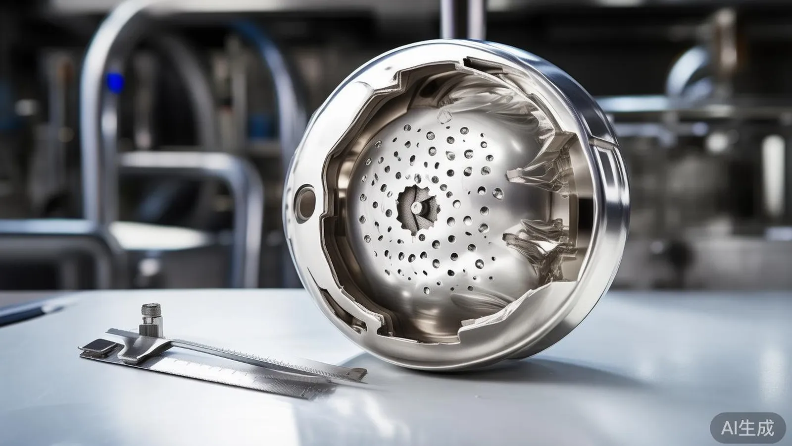
A static spray ball is a hollow sphere with drilled orifices. Liquid enters through the stem, fills the internal chamber and leaves as a set of fixed jets. Nothing in the device moves. The pattern is fixed at the moment the holes are drilled.
That simplicity is the reason it lasts. There is no rotor to seize, no bearing to wear and no turbine to stall on debris. The trade is that flow and pressure must be right from the start, because the ball cannot compensate later.
A rotating head or a rotary jet head for tank cleaning sweeps the wall over time. It can cover a large vessel at lower flow. A static ball covers by count and angle, so it needs more liquid. The published rule captures the gap at 3 gpm per foot of circumference against 1.5 gpm per foot.
Static spray balls for cleaning tanks suit small to medium vessels with simple geometry. They fit totes, drums, small fermenters, mixing tanks and short silos. They also suit any tank where a moving part is unwelcome.
The rest of the CIP tank washing system sets the chemistry and the time. The ball sets only the contact, and contact is where cleaning starts.
Sizing the Orifice: Flow, Pressure and Hole Count
Every spray ball sizing exercise starts from the total flow the vessel needs. Take the flow rule as the target, then divide by the number of orifices. That gives the duty of one hole.
Work the required hole diameter back from that duty. For water, the orifice relation is:
Q(L/min) = 0.65 x d(mm)^2 x sqrt(P(bar))
Take a 12 L/min total across 24 equal holes. Each hole then passes 0.5 L/min. At 2 bar the rearrangement is:
d = sqrt(0.5 / (0.65 x sqrt(2))) = sqrt(0.5 / 0.919) = 0.74 mm
At 3 bar the same 0.5 L/min needs a smaller hole, because pressure does part of the work:
d = sqrt(0.5 / (0.65 x sqrt(3))) = sqrt(0.5 / 1.126) = 0.67 mm
The table below shows the same relation for common hole sizes.
| Orifice d (mm) | Q at 1 bar (L/min) | Q at 2 bar (L/min) | Q at 3 bar (L/min) |
|---|---|---|---|
| 0.5 | 0.16 | 0.23 | 0.28 |
| 0.8 | 0.42 | 0.59 | 0.72 |
| 1.0 | 0.65 | 0.92 | 1.13 |
| 1.5 | 1.46 | 2.07 | 2.53 |
| 2.0 | 2.60 | 3.68 | 4.50 |
Pressure and flow follow the square law. If you know one flow, the next one is:
Q2 = Q1 x sqrt(P2 / P1)
A hole rated 0.5 L/min at 2 bar passes 0.5 x sqrt(1.5) = 0.61 L/min at 3 bar. The spray angle does not change with pressure. Only the flow and the droplet energy do.
Spray ball sizing that stops at the total flow is half done. The split across the holes, and the diameter each hole needs, decides whether the ball can deliver the figure on the label.
The Spray Ball Nozzle Hole Pattern
The spray ball nozzle hole pattern is a set of rings, not a random scatter. Each ring sits on its own latitude of the sphere and carries its own hole angle. Together they aim at a band of the vessel wall.
A common layout runs an upper ring, an equator ring and two to three lower rings. The upper ring angles steeply downward to reach the top head and the shoulder. The equator ring points nearly horizontal to strike the sidewall square.
The lower rings flatten as they go down, then steepen again at the base. That lets them reach the lower shell and the cone without leaving a gap at the knuckle.
The reason for the angle spread is simple geometry. A jet from the top of the ball meets the wall at a shallow angle, close below the head. A jet from the bottom has to travel further and hit a surface that curves away. Aiming each ring at its own band gives every part of the wall a direct strike.
Rows are spaced so that adjacent impact circles overlap. Published practice calls for 10 to 15 percent overlap. Below that, a ring of dry wall can survive between two wet bands.
The tank cleaning nozzles overview sets this pattern work against other head types.
Coverage Math on the Vessel Wall
Each jet leaves a hole as a narrow cone. The impact circle on the wall grows with distance. For a full cone angle theta and a throw distance L, the impact radius is:
r = L x tan(theta / 2)
Take a 15 degree cone and a 600 mm throw. The radius is 600 x tan(7.5) = 600 x 0.132 = 79 mm. The patch is about 158 mm across.
A 24 hole ball then covers 24 discs of that size. Each disc is pi x r^2 = 0.0196 m2. The 24 discs total 24 x 0.0196 = 0.47 m2. Compare that with the wetted wall area of the vessel.
The comparison gives a coverage coefficient. Divide the total footprint area by the internal surface area. Keep the result at 1 or above, and add the overlap margin on top. A figure below 1 means at least one patch of wall sees no direct jet.
The footprint is only the direct strike. Between the jets, cleaning depends on the film that runs down the wall under gravity. That film carries soil away, but it carries it from surfaces the jet already wetted. It does not rescue a dry shadow.
Distance also thins the jet. Droplets slow as they travel, and the air drag on a small drop is high. Published guidance notes that throw distance, not just pressure, sets the useful reach. A coarse jet carries further than a fine one at the same pressure.
For a static ball on a vessel above about 1.5 m across, published practice often uses two or three balls. They are spaced to cut the throw distance per ball. The published flow rule for spray balls for cleaning tanks is written per foot of circumference, so convert the units before sizing a metric vessel. Spray ball sizing should be checked against the footprint total before a body is ordered.
Rib Body and Full Sphere
CIP spray balls divide into two body classes by geometry, not by brand. The rib body, sometimes called a mini ball, carries holes over a limited arc. The full sphere carries holes over the whole ball.
The rib body is a smaller, often slotted head. Its holes face one general direction and its arc runs from about 180 to 270 degrees. It suits totes, drums and small tanks where the far wall is close.
The full sphere wraps its holes around the whole ball. It throws in every direction, so one device can cover a tall or wide vessel from a single top entry.
| Attribute | Rib or mini body | Full sphere |
|---|---|---|
| Coverage arc | 180 to 270 degrees | 360 degrees |
| Typical hole count | 8 to 30 | 20 to 80 |
| Typical total flow | 20 to 80 L/min | 100 to 400 L/min |
| Vessel fit | totes, drums, tanks under about 1.5 m | tanks above about 1.5 m |
| Mounting | side or top, small footprint | top centre, needs headroom |
| Main risk | leaves the far wall in shadow | channels if flow is short |
A rib body is the usual choice for an IBC tote spray ball, because the tote is small and the flow is modest. The IBC tote spray ball often mounts on a clip or a threaded stem at the top hatch.
A full sphere with too little flow is worse than a rib body with the same flow in a small tank. The full sphere spreads the liquid thin in every direction, so no single jet reaches far. Match the class to the vessel before matching the number.
Order CIP spray balls by body class, hole count and connection, not by a single flow figure. A tote and drum rinse station shows the same sizing at small scale, with the ball and the return line set together.
Pressure Drop and Pump Duty
The pressure you read at the pump is not the pressure at the orifice. The ball, the line and the fittings each take a share. Published data for a static ball often shows 1.5 to 1.7 bar of drop across the device at a mid range flow. That is a design guide, not a fixed value.
Add the losses in order: the orifice duty pressure, the ball internal loss, the line friction, the fitting losses and the elevation head. Then add a margin. A static ball rated to 5 bar should not see 4.8 bar after losses, because a fouled line will use the rest.
Pump hydraulic power follows from flow and pressure:
kW = Q(L/min) x P(bar) / 612
A CIP pump at 234 L/min and 3 bar draws 234 x 3 / 612 = 1.15 kW of hydraulic power. A small tote station at 12 L/min and 2 bar draws 12 x 2 / 612 = 0.039 kW. Electrical draw will be higher, because the motor and the pump are not loss free.
A single static ball in a tall vessel can also need a second supply line. One line feeds the ball at the flow it needs, and a second line feeds a second ball if the throw distance is too long.
Matching Vessel Size to Ball and Flow
Vessel size drives the class and the flow. The table below keeps the published circumference rule in view. Treat the numbers as a starting band and confirm them with a coverage test.
| Vessel | Approx internal surface | Ball class | Flow band |
|---|---|---|---|
| 1,000 L IBC tote | 4 to 6 m2 | rib or mini body | 20 to 60 L/min |
| 2 m x 3 m fermenter | 20 to 30 m2 | full sphere, one device | 200 to 250 L/min |
| 3 m x 6 m dairy silo | 60 to 80 m2 | full sphere, two or three | 300 to 400 L/min |
The 2 m fermenter is the case worth noting. Its 20.6 ft of circumference puts the rule at 62 gpm, or about 234 L/min, which sits inside the band. A tank with a full height agitator shaft may need a retractable or shaft pass through design instead.
For the wider duty, the tank and vessel cleaning application sets the context across food, pharma and chemical service.
Materials and Sanitary Design
Spray balls for cleaning tanks are usually made from 304 or 316L stainless steel. The 316L grade resists chloride and caustic attack better, so it is the usual choice for pharma and for any vessel that sees aggressive chemistry.
A sanitary spray ball is built to remove every place a soil can hide. The surfaces are smooth, the joints are welded or gasketed with no crevice, and the body drains by gravity. A published finish target for hygienic work is Ra 0.8 micron or finer on product contact surfaces.
The public standards that govern this class carry well known names. The 3-A sanitary standards set construction and finish for dairy and food equipment. The EHEDG guidelines cover hygienic design and cleanability. ASME BPE covers bioprocessing equipment, including the riboflavin coverage method.
CIP spray balls for pharma service usually call for 316L, while 304 covers lighter food duty.
A sanitary spray ball also needs a matching connection. Clip on, weld on and threaded stems each suit a different tank head. The tank cleaning product range groups these by body and connection. Plastic bodies suit low pressure tote work, and the plastic nozzle range covers those grades.
Material is not automatically the answer. A polished ball with the wrong spray ball nozzle hole pattern still leaves a shadow. The finish helps the soil release, but the spray ball nozzle hole pattern decides where the liquid goes.
The Spray Ball Coverage Test
A spray ball coverage test proves that the pattern reaches every internal surface. It does not prove that the soil was removed. It proves contact, which is the step before removal.
The standard tracer is riboflavin. The solution is prepared at about 0.2 g/L and sprayed over the dry internal surfaces. Under UV light at about 365 nm the film glows yellow green, so coverage is visible to the eye.
The vessel is then rinsed on the planned CIP cycle. After the rinse the surfaces are inspected again under UV light. A pass means no visible fluorescence anywhere on the wall. ASME BPE specifies the riboflavin solution method, and EHEDG guidance supports the same idea.
A spray ball coverage test fails for reasons that are not always real. Powder that never fully dissolved sticks to the wall and glows. Gaskets and seals trap dye and release it after the rinse. Inspect the ball itself as well, because a droplet left on a hole can read as residue.
The second test proves residue removal. Swab ATP measures the soil left after the clean. Published pass bands for common luminometers sit near 10 to 20 RLU for a pass and 30 to 60 RLU for a fail. The exact number belongs to the instrument and the facility, so set it from your own data.
Run a spray ball coverage test before the initial production run, then repeat it after any change to pressure, flow or hole count. A spray ball CIP retrofit shows why the retest matters after a hardware change.
Common Sizing Mistakes
The mistakes repeat across plants, and each one leaves a shadow.
Sizing a static ball on the rotating flow rule is the most common. The rotating figure is half the static figure. A ball built for 1.5 gpm per foot will run dry at the top of a tall vessel when it is fed that flow.
Raising pressure to make up for low flow is the next. Pressure lifts velocity, but it cannot lift the volume that a hole count demands. A static ball short on flow stays short on coverage at any pressure.
Ignoring orifice wear is the quiet one. A hole that grows 10 percent in diameter passes 21 percent more liquid. Flow drifts upward, the certificate no longer matches the machine and the CIP balance goes off. Track nozzle wear before it becomes silent over-application, because a worn ball oversprays as quietly as it undercovers.
Using one ball for a long vessel is another. Throw distance grows with length, and the far end of a tall tank falls outside the useful reach. Two or three smaller balls often beat one large one. Spray ball sizing that ignores wear and reach together drifts out of balance on both ends.
Blocked holes finish the list. A blocked hole removes a jet and its band of coverage at the same time. Check the strainer before blaming the ball.
Frequently Asked Questions
How do I calculate flow per hole on a spray ball?
Divide the total flow by the hole count. A 12 L/min ball with 24 holes gives 0.5 L/min per hole. Then back the diameter out of Q = 0.65 x d^2 x sqrt(P). At 2 bar that same 0.5 L/min needs a 0.74 mm hole.
What pressure does a static spray ball need?
Most static spray balls run at 1 to 5 bar (15 to 70 psi). Higher pressure raises jet velocity as the square root, so 3 bar gives about 1.4 times the flow of 1 bar. The ball rated maximum sets the ceiling, and the pump curve sets what you can hold.
What is a spray ball coverage test?
It is a tracer test that confirms the spray reaches every internal surface. Riboflavin is sprayed on the dry wall, viewed under UV light, rinsed on the CIP cycle and viewed again. No glowing film after the rinse means the coverage passed.
Can a CIP spray ball be sized for an IBC tote?
Yes. A small tote usually takes a rib or mini body at 20 to 60 L/min. The IBC tote spray ball mounts on a clip or a threaded stem at the top hatch. Confirm the pattern with a coverage test, because a tote has corners that a round pattern may not reach.
How much does orifice wear change spray ball flow?
Flow scales with the square of the hole diameter. A 5 percent diameter gain adds about 10 percent flow, and a 10 percent gain adds about 21 percent. Recheck the total flow against the certificate at each service, and replace worn bodies rather than opening the pressure.
Does a sanitary spray ball need a specific connection?
Choose the connection that matches the tank head and the cleaning loop. Clip on and weld on stems suit permanent hygienic installations, and threaded stems suit retrofits. A mismatch in connection is a crevice risk, not just a fit problem.
The Bottom Line
Spray ball sizing comes down to flow per hole, hole pattern and throw distance. Get the flow split right and aim each ring at its own wall band. Then prove the result with a riboflavin coverage test and a swab ATP check. Pressure cannot repair a pattern that never aimed at the shadow.
The cost of a missed patch is not the water or the caustic. It is the batch that leaves the tank with residue in one strip. It then fails a swab and forces a hold, a re-clean and a re-sample. A sizing review before the run is cheaper than a recall after it.
Bring your vessel dimensions, your flow and your cycle to request a spray ball sizing review. We will match a body, a flow and a pattern to the tank.
Next Step
Send the Duty. Get Sized Nozzles Back.
Send your flow, pressure, fluid and target coverage. We come back with nozzle options and figures, not a catalogue number.
Written by
Ray ChanIndustrial spray nozzle specialist. I size tank cleaning, atomizing, flat-fan and spiral nozzles against real duty conditions, flow, pressure, fluid and target, rather than catalogue numbers. Every guide here comes from actual sizing work.